The DLR-F9 test case
The DLR-F9 model is a high wing transport aircraft. The model was designed 8 to be used for basic flow studies of new geometries and adaptive components in particular near the wing body junction and on the inner parts of the wing. Therefor the model was built in an unusual large scale in order to provide high resolution data in the region of interest and offer sufficient space for instrumentation and adaptive components. The use of such large scale models in a relatively small wind tunnel became possible only in result of the modern adaptive wall technology of the wind tunnel test section. The adaptive ceiling and bottom walls help to avoid wind tunnel blockage with large models.
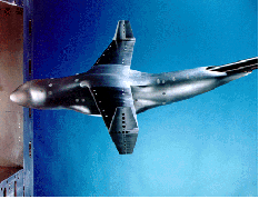
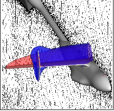
The scale of the model requires the wing's outer parts to be clipped in this given wind tunnel. In order to correct for the effect of the clipped wing, the model is equipped with CCSBs 4. Figure 1 shows the model in the wind tunnel in a virtual view using the data for accompanying analysis in a virtual wind tunnel approach. Figure 3 shows the real model in the wind tunnel.

Figure 3 DLR-F9 model mounted in the Transsonic Wind Tunnel Göttingen TWG.
Several steps are required to set up the CCSB concept. CFD-analysis of the full wing for various lift coefficients verifies a shock location along the wing span which is approximately along a line x/l=const. This is referred to as Isobar Concept.
CCSBs were designed by evaluating the flow field in a plane at the span position where the CCSB was placed on the wind tunnel model. This allowed to design a set of unsymmetrically twisted double sided winglets which worked as side blades controlling the circulation distribution along the cut-off wing. A different twist of the winglets resulted for each desired lift coefficient. Ideally these CCSBs would be adjustable. However, mechanical requirements do not allow for adjustable winglets. Therefore, during the actual experiment, flow parameters such as free-stream Mach number and angle of attack were varied until the flow met the design criteria of the CCSBs. This was controlled using the pressure distribution and shock location. Once the optimal set of flow parameters was identified, the desired data of the flow around the aircraft could be sampled with the flow already being corrected for the undesired side effects of the model scale.
This concept was first examined by numerical flow simulation using the DLR t-code 9 which in this case solved the Euler equations on an unstructured grid around the full airplane configuration, including the wind tunnel mounting system and the walls of the wind tunnel test section. Figure 4illustrates that the simulation proves the similarity of the c flow around the configuration with CCSBs and the configuration with un-clipped wings over a large region of the wing. The influence of the CCSBs should be only local as required. The region of interest close to the wing/body junction is unaffected by the CCSBs. The lift distribution over the wing span is corrected by the CCSBs as desired. A comparison of the iso-surface of Mach number equal to 1 is used as a significant indicator of the similarity of both solutions.

Figure 4 Comparison of wind tunnel model configuration with un-clipped wing and with CCSBs from numerical flow simulation. The iso-surface of Mach-number = 1 is used to prove the concept.
Obviously this expensive simulation of a three-dimensional flow field will only be performed for a limited number of characteristic parameter combinations. For comparison with the wind tunnel data, faster feature extraction algorithms are required.
The run-time data analysis is used to decide whether the concept worked and where the design criteria were met. A rapid and effective detailed analysis of the flow field was necessary. The analysis involved the evaluation of pressure distribution and local lift at various cross sections of the wing as well as an automatic detection of shock position along the wing.


