The DLR-F9 test case
The DLR-F9 model is a generic high wing transport aircraft. The model is designed to be used for basic flow studies of new geometries and adaptive components in particular near the wing body junction and on the inner parts of the wing. Therefore the model was built in an unusual large scale in order to provide high resolution data in the region of interest and offer sufficient space for instrumentation and adaptive components. The use of such large scale models in a relatively small windtunnel became possible only due to the modern adaptive wall technology of the windtunnel test section. The adaptive ceiling and bottom walls help to avoid windtunnel blockage with large models.
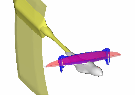
The scale of the model requires the wings outer parts to be clipped in this given windtunnel. In order to correct for the effect of the clipped wing the model is equipped with CCSBs. Fig. 1 shows the model in the windtunnel in a virtual view using the data for accompanying analysis in a virtual windtunnel approach.
Fig. 2 Comparison of numerical simulation of windtunnel flow around the DLR-F9 model with CCSBs and Windtunnel walls (not shown) and flow around a full wing model. Sonic surfaces shown for comparison exhibit no interference near the wing body junction

Several steps are required to set up the CCSB concept. CFD-analysis of the full wing for various lift coefficients verifies a shock location along the wing span which is approximately along a line x/l=const. This is referred to as Isobar Concept. Evaluation of the flow field in a plane at the span position where the CCSB will be placed on the windtunnel model allows to design a set of unsymetrically twisted double sided winglets which work as side blades controlling the circulation distribution along the cut-off wing. A different twist of the winglets results for each desired lift coefficient. Fig. 2 illustrates that the CCSBs may be used to correct the flow field near the wing body junction in the desired way. The figure compares two numerical simulations of the model equipped with full wings and clipped wings with CCSBs and windtunnel walls in place. By comparing the shape of the sonic surface (Ma=1) in the flow field one can obtain a good impression of the local influence of CCSBs.
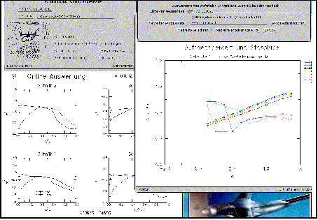
Ideally these CCSBs would be adjustable. However, mechanical requirements don't allow for adjustable winglets. Therefore, during the actual experiment flow parameters such as free-stream Mach number and angle of attack were varied until the flow meets the design criteria of the CCSBs. This was controlled using the pressure distribution and shock location. Once the optimal set of flow parameters was identified, the desired data of the flow around the aircraft could be sampled with the flow already being corrected for the undesired side effects of model scale. In order to decide whether the concept worked and where the design criteria were met a rapid and effective detailed analysis of the flow field was necessary. The analysis involved the evaluation of pressure distribution and local lift at various cross sections of the wing as well as an automatic detection of shock position along the wing.
Fig. 3 Screenshot of the F9-Online data evaluation system: The main control panel positioned top left offers various flow evaluation tools, bottom left a series of pressure distribution plots for various cross sections, on the right integrated lift coefficients and shock position in comparative visualisation, video surveillance of the model in the windtunnel for additional control of vibration.


